Geometry Tools
Geometry tools heavily utilise the point selection workflow.

Left Mouse selects the current point.
Esc exits without making changes.
Ctrl fixes the current selection plane.

Point selection respects Blender's snapping mode; when snapping is disabled, point selection will not snap.
Weld
Weld is a context aware action that follows a geometry tool invocation. In applicable cases, a Weld will be available. Press W to Weld.
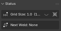
The next Weld can be seen in the Anvil status panel.
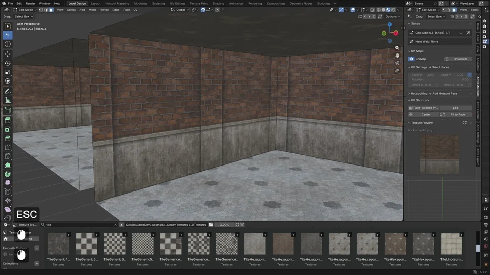
Box Builder
Press B to build a box.
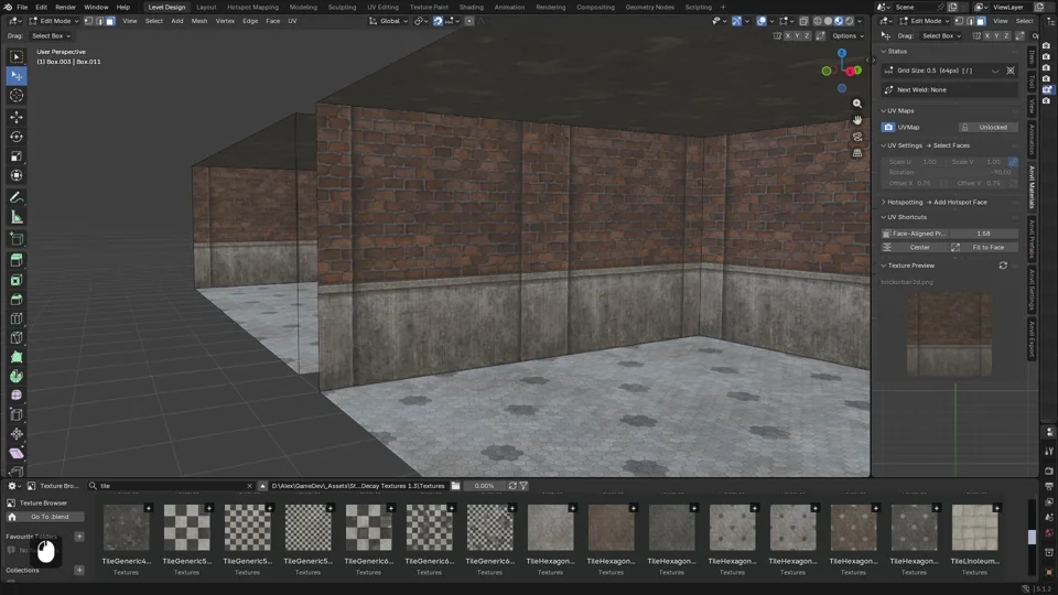
Click once to set the start point; click a second time to define the area; click a third time to extrude and instantiate the box. Holding the mouse button is not required.
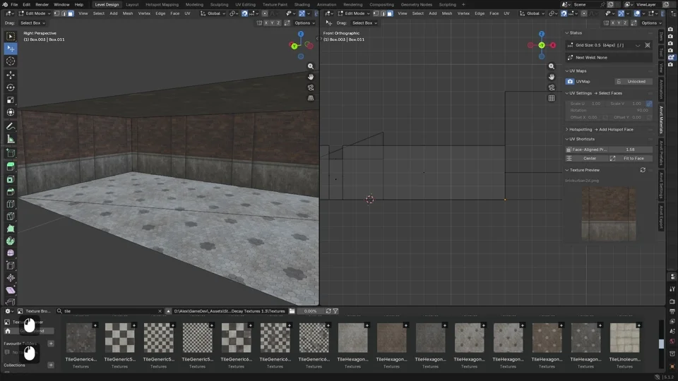
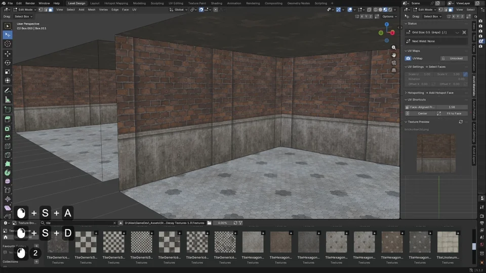
Box Builder will use the last selected texture (either a selected face, or an image selected in the image browser).
Box Builder works in object and edit mode.
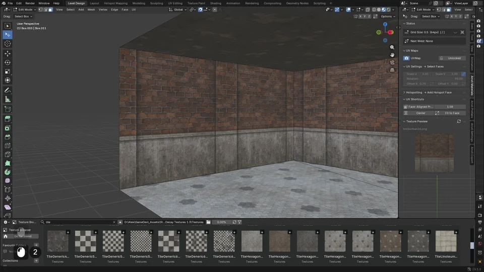
A 0 length extrusion box becomes a plane.
Defining the initial area as a line will lead to a vertical plane.
Holding Shift during the first click will modify the workflow. Click once to set a start point; click a second time to define an initial line; click a second time to define the area; click a third time to extrude and instantiate the box.
This allows non-grid aligned boxes.
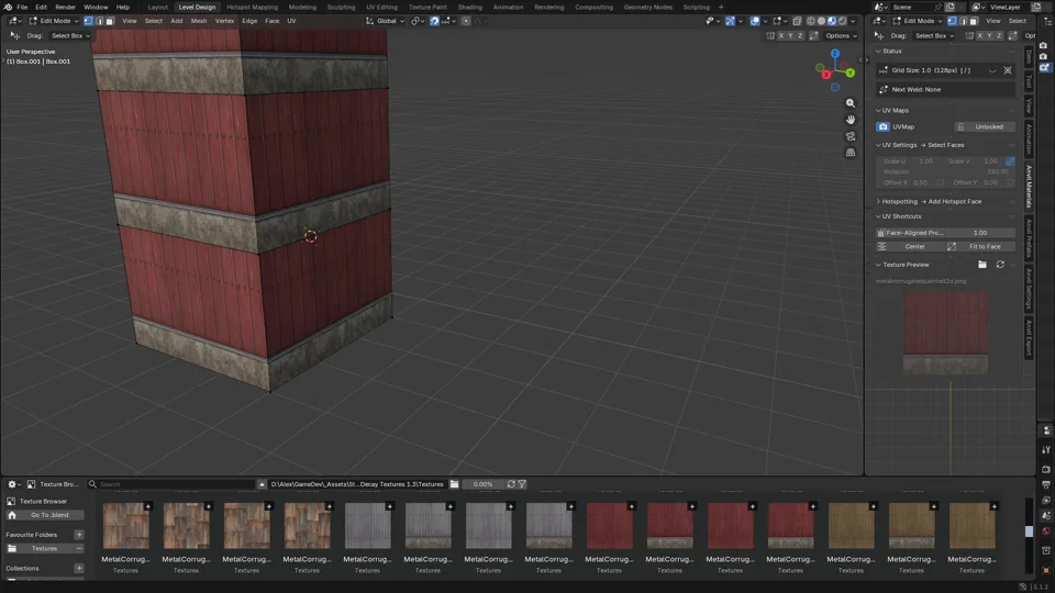
After building a box, Weld W will invert faces. Useful for interiors!

Cube Cut
Press C to perform a Cube Cut. Cube Cut works only in edit mode.
A cube cut eliminates all geometry inside the cube and adds edges to connected geometry to avoid T-Junctions. It is intended for cutting holes in meshes.
Click once to set the start point; click a second time to define the area; click a third time to extrude and remove everything inside the box (holding Shift will have the same effect as in Box Builder). Holding the mouse button is not required.
Like Box Builder, Cube Cuts can be flat planes.
If a cube cut results in 2 edge loops, Weld W will bridge the loops, creating a corridor.
If a cube cut results in a single edge loop, Weld W will extrude and cap into the space defined by the cut, creating an alcove.
Cube Cut works in orthographic mode. In orthographic mode, Cube Cut has infinite depth.

If there is an active selection of faces, Cube Cut will only apply to the selection. Use face selection to avoid unecessary cuts in orthographic mode.